
Blog
Feeder setup has a direct effect on placement accuracy because it defines the relationship between the component in the tape, the machine’s pickup point, the vision system, and the PCB coordinates. A placement head can be mechanically precise and still produce skewed parts, pickup failures, or inconsistent placement when the feeder is mounted incorrectly, indexed poorly, or loaded with unsuitable material.
For operators, feeder-related errors are easy to misread. A component shifted in the same direction on several boards may look like a program offset. Repeated no-picks may appear to be a nozzle or vacuum issue. In many cases, however, the source is simpler: the feeder is not presenting the component at the expected position or orientation. Establishing a disciplined feeder setup process is therefore one of the fastest ways to improve the stability of SMT Pick and Place Machines.
The feeder is part of the placement accuracy chain
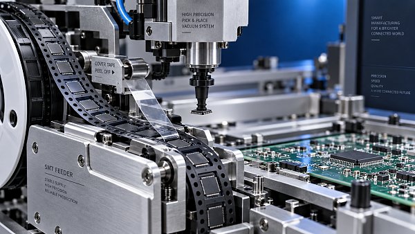
Placement accuracy is often discussed as a machine specification, but the published accuracy of a pick-and-place machine assumes controlled inputs. The feeder must advance the tape by the correct pitch, hold the pocket in a repeatable pickup location, peel the cover tape without disturbing the component, and maintain a stable mechanical position in the feeder bank.
If any of these conditions varies, the machine may still move exactly as commanded while the part is no longer where the program expects it to be. Vision correction can compensate for some pickup-position variation, especially when bottom vision is used. It cannot solve every problem. A component that has shifted within its pocket, has been lifted by the cover tape, or is presented at an unstable height may be difficult to recognize, may be picked off-center, or may rotate during travel.
The practical question is not whether the feeder has been installed in the machine. It is whether it repeats the same presentation condition through the full production run. A feeder that works for the first few boards but drifts after several hundred advances is not accurately set up, even if it passes an initial manual check.
Mounting position and feeder identification must agree
On machines with intelligent feeder recognition, setup begins with confirming that the physical feeder location, feeder ID, and programmed component assignment match. This may sound routine, yet mismatches remain a common source of avoidable defects after line changeovers, feeder replacement, or offline preparation.
A feeder installed one slot away from its expected position can produce an immediate wrong-part condition. More subtle errors occur when the correct feeder is mounted but the wrong tape pitch, package definition, rotation value, or pickup coordinate is associated with it. Operators may then see a consistent rotation or placement offset that affects only one reference designator group or one component value.
Mechanical seating matters even when the feeder ID is correct. The feeder should fully engage with the machine rail and locking mechanism. Dirt, bent latches, worn locating features, or cable interference can leave the feeder slightly proud of its intended mounting plane. Small movement at the feeder body can become significant at the pickup point, particularly for fine-pitch passive components, small-outline devices, and parts with tight land-pattern tolerances.
- Verify the feeder location against the active setup list before enabling production.
- Confirm the feeder is locked and cannot move laterally or vertically under light manual pressure.
- Check that feeder communication, if used, is functioning before relying on automatic verification.
- When replacing a feeder during a run, confirm that its loaded tape, pitch setting, and assigned component data match the removed feeder.
A barcode or intelligent-feeder system reduces setup mistakes, but it does not replace physical inspection. It can confirm identity and location; it cannot determine whether the tape is routed correctly, whether a pocket is damaged, or whether the feeder is advancing smoothly.
Tape pitch and pocket geometry determine where the nozzle picks
The machine needs to know where each component pocket will stop after indexing. This depends on tape pitch, hole pitch, pocket spacing, and the feeder’s advance mechanism. A 4 mm pitch tape and an 8 mm pitch tape may look similar at a glance, but the feeder indexing logic and programmed settings must correspond to the actual carrier tape.
Pitch-related faults often create intermittent behavior. The first component may be presented correctly, while the next is partly covered, stopped between positions, or advanced too far. This can lead to no-picks, body contact with pocket walls, bent leads, or component rotation during pickup. Operators should not assume that an apparently functional feeder is correctly indexed simply because it advances the tape.
Carrier tape condition is equally important. Pockets must retain the component without allowing excessive movement, yet release it cleanly when the nozzle picks. Deep or oversized pockets can allow small chips to rotate or slide. Shallow pockets may leave parts exposed to cover-tape tension. Deformed embossed tape, crushed pockets, and damaged sprocket holes can cause a feeder to advance inconsistently even when the feeder mechanism itself is in good condition.
For critical parts, inspect several indexed positions rather than only the pickup pocket visible at setup. Look for components sitting flat, centered within the pocket, and clear of the pocket edge. If parts appear to climb out of pockets after the cover tape has been peeled, the issue may be related to cover-tape tension, tape quality, static charge, or a mismatch between the feeder and tape format.
Do not treat tape width as a complete setup description
Two reels with the same nominal tape width can require different handling. Component thickness, pocket depth, cover-tape adhesion, and reel winding condition all affect how the tape behaves at the peel point. A feeder that handles one 8 mm reel reliably may be unstable with another 8 mm reel containing a lighter component or a different pocket design.
This is particularly relevant when using substitute packaging, components from multiple approved sources, or reels that have been reloaded into a feeder. The electrical component may be equivalent while the carrier tape behavior is not. If the package presentation changes, the feeder setup should be checked again rather than assumed to remain valid.
Orientation errors begin before the component reaches vision
Component orientation has two layers: the orientation inside the tape pocket and the rotation defined in the placement program. Both must be correct. A reel may be loaded with the component rotated relative to the assumed tape orientation, or a feeder may be set up from the opposite tape direction. The result can be a consistent 90-degree, 180-degree, or mirrored placement error.
Vision systems can identify polarity marks, leads, or body outlines when the part definition supports it. That capability should not be used as a reason to skip orientation verification. Vision inspection may be less reliable for symmetric packages, poorly marked devices, reflective surfaces, or components whose polarity feature is partly obscured by the nozzle. A passive component may place successfully despite an incorrect nominal rotation, while a polarized capacitor, diode, connector, or integrated circuit may create a functional defect.
The safest setup sequence is to compare the actual first component in the pickup position with the feeder drawing, the CAD or centroid rotation convention, and the board reference orientation. Run a controlled first-article check after placement, not only after pickup. A part can look correct in the camera yet still be rotated incorrectly relative to the PCB footprint if the program’s rotation convention is wrong.
Polarity-sensitive parts deserve a separate verification point during changeover. This should include the reel label, component marking where visible, tape orientation, and board placement result. Treating all feeders identically during setup creates risk because the consequence of an orientation error varies sharply by component type.
Cover tape control affects pickup repeatability
Cover tape is often overlooked because it is removed as part of normal feeder operation. Its peel angle and tension influence whether the component remains stable in the pocket immediately before pickup. Excessive tension can lift light parts, drag them toward the peel side, or cause them to tilt. Insufficient control can leave cover tape in the pickup path, snag the tape, or produce irregular peeling.
A consistent cover-tape path should be maintained from reel entry to waste collection. The tape should not rub against adjacent feeders, machine guards, or loose cables. It should also be collected so that it cannot pull back into the feeder or interfere with the placement head. When a feeder arrangement is dense, cover-tape routing becomes a practical accuracy issue rather than a housekeeping detail.
Static electricity can compound this problem. Very small passives, thin plastic packages, and lightweight parts may cling to the cover tape after peeling. Operators may observe missing components at the pickup point, or parts that appear present but are lifted enough to defeat reliable vacuum pickup. The appropriate response depends on the material and line controls, but the diagnostic principle is straightforward: inspect the component behavior at the peel point before changing nozzle or vision parameters.
Feeder maintenance is accuracy maintenance
Feeders wear in ways that do not always cause an immediate alarm. Sprocket pins can become worn, tape guides can accumulate debris, clamps can lose stiffness, and drive mechanisms can develop backlash. These conditions may create small indexing variation that becomes visible only on fine-pitch or miniature packages.
Operators should watch for symptoms rather than waiting for a complete feeder failure. Repeated no-picks from one feeder, random pickup-angle changes, irregular tape advance, inconsistent pocket stop position, and excessive force needed to load tape all justify inspection. Replacing a nozzle, adjusting vacuum, or editing pickup coordinates may temporarily mask the issue while leaving the feeder as the underlying source.
A useful maintenance routine includes cleaning tape-contact surfaces, checking sprocket and guide condition, verifying that locking features engage securely, and testing feeder advance with the tape type normally used in production. Where the machine or feeder manufacturer provides calibration or service procedures, those procedures should be followed rather than relying on improvised adjustments. Mechanical changes made to compensate for one reel can create a wider repeatability problem for later jobs.
How to isolate feeder setup from machine and program faults
When placement defects appear, the fastest diagnosis comes from looking at the pattern of failure. A feeder-related issue usually follows a specific feeder, reel, or component position. A machine-axis or board-support issue is more likely to affect multiple components across a broader area. A programming issue commonly produces the same offset or rotation on every occurrence of the affected component.
A short, controlled check can separate these causes:
- Stop after a small number of placements and inspect the pickup position, nozzle centering, and placed component location.
- Swap the suspect reel into a known-good compatible feeder, or move the feeder assignment according to approved setup controls. If the defect follows the reel or feeder, investigate the presentation system first.
- Compare the component in the tape pocket with the programmed package and pickup data.
- Check whether the defect is consistent, progressive, or random. Progressive errors often point to tape advancement, cover-tape behavior, or reel winding.
- Use first-article placement inspection to distinguish pickup accuracy from PCB alignment, fiducial recognition, or board support problems.
Changing multiple variables at once makes diagnosis harder. If vacuum level, feeder position, vision threshold, and placement offset are adjusted together, the line may resume temporarily without revealing which condition caused the fault. For recurring jobs, that uncertainty becomes expensive because the same issue returns at the next setup.
A setup standard should focus on repeatability, not just startup
The best feeder setup standard is one that verifies the condition operators need during production: correct component identity, correct physical location, correct tape presentation, stable cover-tape peeling, and repeatable pickup. It should also define when an operator should stop and escalate rather than compensate through program edits.
For SMT Pick and Place Machines, the feeder is not a passive accessory at the edge of the machine. It is the first positioning device in the placement process. A well-maintained machine cannot recover consistent accuracy from a component that arrives at the nozzle in an inconsistent position. When placement quality begins to drift, checking feeder seating, tape indexing, orientation, and peel behavior early will often produce a clearer answer than starting with machine calibration.


GET A FREE QUOTE
Simply fill in the information to get a free quote! Our professional team customizes photovoltaic solutions for you, provides accurate quotes, and rejects hidden consumption!