
Blog
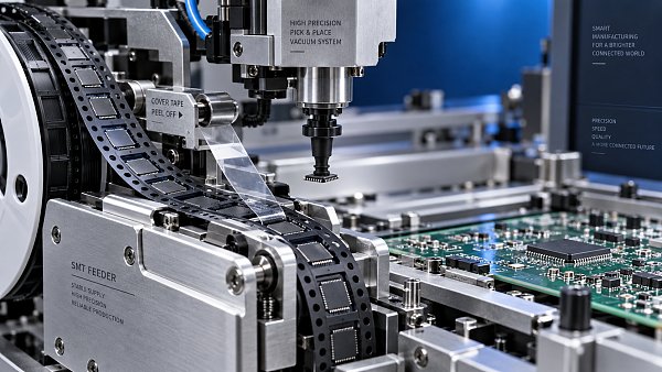
SMT feeders affect placement stability by determining how consistently each component arrives at the pickup point. If the tape advances unevenly, the feeder moves in its mounting slot, or the component is disturbed during cover-tape removal, the nozzle may pick it up off-center, fail to collect it, or carry it insecurely. These problems can occur even when the placement machine is correctly calibrated.
The relationship is not always direct: a component picked up slightly off-center may still be placed accurately if the machine’s vision system measures and corrects its position. However, vision cannot reliably compensate for a missing component, physical damage, or a part that shifts on the nozzle after inspection. Stable feeding gives the placement head a repeatable starting condition and reduces the number of errors the machine must handle.
Placement stability begins before the nozzle reaches the PCB
A tape feeder must advance the carrier tape by the programmed component pitch, expose the next pocket, and hold it steady while the nozzle descends. The component must be accessible at the expected height and within the machine’s pickup window. Consistency across repeated cycles matters more than a single successful pickup.
Consider a small semiconductor package sitting loosely in its tape pocket. If indexing stops abruptly or cover-tape peeling disturbs the carrier, the package may rotate or tilt before pickup. The nozzle can then contact an edge instead of a suitable surface. That changes the vacuum seal and how securely the part is held during head movement.
Larger packages present different challenges. Their mass, pocket depth, and available pickup surface can make tape support and pickup height more significant. A feeder that handles one component reliably may therefore need different settings, or a different configuration, for another package.
Feeder repeatability and placement accuracy are related, but they are not interchangeable. A stable feeder supports accurate placement; it does not correct an unsuitable nozzle, incorrect component data, poor board support, or an error in the machine’s coordinate calibration.
Which feeder conditions cause inconsistent pickup?
Tape indexing and mechanical wear
The indexing mechanism positions the tape using its sprocket holes. Wear, contamination, damaged engagement points, or excessive mechanical play can make the final pocket position vary between cycles. Incorrect pitch settings can also present the wrong position or prevent the pocket from lining up with the pickup opening.
A consistent position error and a variable position error require different responses. A repeatable offset may be addressed through the machine’s approved feeder adjustment or pickup-position procedure. Random movement suggests a mechanical, tape-guidance, or seating problem. Changing coordinates to compensate for random movement can hide the symptom briefly while leaving the cause active.
Watch for errors that appear after repeated indexing, after a reel change, or only during sustained production. Such patterns can help distinguish an incorrect setup from wear or inconsistent tape movement.
Feeder seating and pickup height
A feeder can index correctly and still present components poorly if it is not securely seated. Debris on the mounting interface, a worn latch, or damage to a locating surface can allow movement or change the feeder’s position relative to the head.
Height matters as much as horizontal alignment. If the nozzle descends too far, it may press the component against the pocket or contact the carrier tape. If it stops too high, it may fail to establish a reliable vacuum seal. The correct pickup height depends on the component, pocket geometry, feeder arrangement, and machine setup.
Inspection should therefore include the mounting interface and tape support, not just the drive mechanism. A feeder that looks serviceable on a workbench may behave differently when locked into a worn or contaminated machine slot.
Cover-tape peeling and reel resistance
Cover tape must be removed smoothly enough to expose the component without disturbing it. Excessive or uneven peeling force can tug the carrier tape, shake parts inside their pockets, or interfere with indexing. Loose cover tape can obstruct the pickup area if it is not routed and collected correctly.
Reel handling also affects feeding. A reel that binds against its holder or a poorly routed tape path creates variable resistance upstream of the pickup point. A nearly empty reel, a different tape material, or a newly loaded reel may change the feeding conditions. These changes do not automatically mean the feeder has failed, but they deserve attention when errors begin after a material change.
Why smaller components reveal feeding problems sooner
Small components leave less room for pickup-position variation. A displacement that a larger package tolerates may put the nozzle close to the edge of a smaller part. Lightweight components can also be more easily disturbed by tape motion, peeling, or vibration.
Package shape influences the result. A flat package with a suitable pickup surface may remain secure despite a modest initial offset. A component with a restricted pickup area or uneven top surface may require more precise presentation and a carefully selected nozzle. Feeder condition should be assessed alongside these package-specific requirements.
Production speed can expose an otherwise hidden weakness. Faster cycling gives the tape and component less time to settle, depending on the feeder and machine design. If feeding improves when an approved indexing or pickup timing setting is adjusted, that is useful diagnostic evidence. It does not establish whether the underlying cause is wear, unsuitable settings, or difficult packaging.
Electronic feeders can provide controlled indexing and communication with compatible machines, but electronic control alone does not guarantee stable pickup. Mechanical condition, tape routing, mounting, and component presentation still determine whether the commanded movement produces the expected result.
Use the defect pattern to locate the cause
A feeder problem often produces a recognizable pattern, but no single symptom proves the diagnosis. Vacuum failures can also come from a blocked nozzle, leakage, or an unsuitable pickup surface. Placement offsets can arise from component-library settings, vision recognition, board alignment, or head calibration.
Machine records are especially useful when they separate pickup failures, vision rejects, retries, and placement inspection results. An increase in retries can reveal unstable feeding even while finished boards remain acceptable. Looking only at final placement defects may miss a feeder that is already reducing throughput.
Also distinguish placement results measured before reflow from defects found afterward. A component that moves during soldering may be affected by paste deposits, pad geometry, or thermal behavior. Its final position alone does not establish that the feeder or placement head caused the movement.
A practical way to isolate feeder-related errors
Start with the affected component and its operating conditions. Record the feeder identity, slot, reel, nozzle, package data, and when the fault occurs. This creates a useful baseline and prevents several simultaneous changes from making the result difficult to interpret.
- Inspect loading and presentation. Check that the tape is engaged correctly, the programmed pitch matches the packaging, the pocket is exposed, and the reel and cover tape move freely.
- Check seating and visible condition. Examine the latch, locating surfaces, guides, and pickup area. Remove contamination using the specified maintenance method.
- Observe repeated indexing. Use the machine’s approved diagnostic procedure to check whether successive pockets stop consistently and components remain settled.
- Substitute a known-good compatible feeder. Keep the component reel, nozzle, and program consistent where practical. A clear improvement makes the original feeder or its setup a stronger suspect.
- Separate feeder, slot, and material effects. A controlled slot change or reel substitution can help identify whether the problem follows the feeder, the mounting location, or the tape.
Change one condition at a time. Moving a feeder, replacing the nozzle, changing pickup coordinates, and reloading the tape together may restore production, but it leaves the cause unclear. That uncertainty makes recurrence harder to prevent.
When examining pickup position, use the machine’s supported camera or diagnostic view rather than reaching into moving equipment. Avoid informal bending, shimming, or aggressive lubrication. These adjustments can change alignment, contaminate components, or interfere with mechanisms designed to operate under specific maintenance conditions.
What to check when choosing a feeder or replacement part
Compatibility starts with the exact placement-machine model and feeder interface. Tape width alone is insufficient. The feeder must also support the required pitch, carrier-tape characteristics, pocket geometry, pickup access, and any communication or software requirements of the machine.
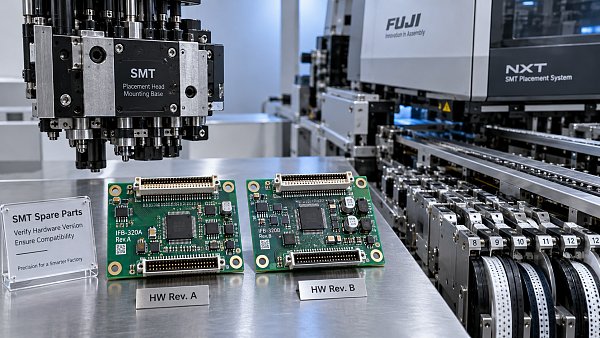
For replacement parts, matching appearance is not enough. A gear, guide, latch, or peeling assembly must match the intended feeder version and fit correctly. Small differences at locating or drive surfaces can affect presentation even when the assembly appears to operate normally.
An original spare part can simplify specification matching when its part number and revision suit the feeder. It does not resolve wear elsewhere in the assembly. Replacing a damaged drive component while leaving a loose mounting interface or worn tape guide may produce only a partial improvement.
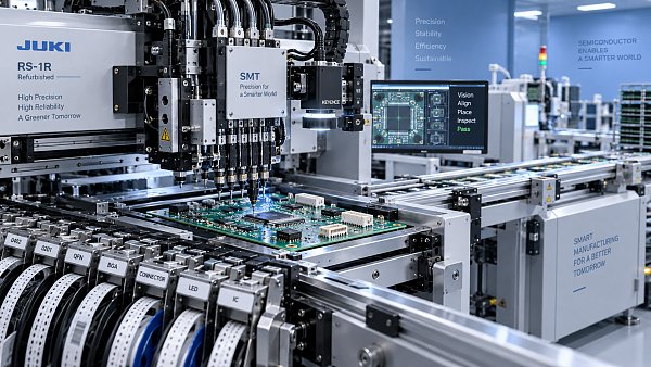
Used or refurbished feeders should be assessed through repeated operation with representative components. Smooth empty indexing does not demonstrate stable component pickup under reel resistance and cover-tape load. The evaluation should include the conditions that matter in production, particularly small packages or tapes associated with recurring errors.
SMT MALLS focuses on SMT/THT assembly equipment, original machine spare parts, and complete PCB assembly line solutions. For feeder-related sourcing, useful starting information includes the machine model, feeder identification, tape format, component package, and observed fault pattern. These details help define whether the requirement concerns a spare part, a replacement feeder, or a wider equipment compatibility issue.
Maintenance should preserve repeatability
Feeder maintenance works best when it addresses the areas that control tape position and component presentation. Guides, sprocket engagement, mounting surfaces, peeling mechanisms, and waste-tape handling deserve regular attention. Cleaning and lubrication should follow the relevant maintenance procedure; adding lubricant indiscriminately can attract debris or affect tape handling.
Track faults by feeder identity as well as component number. Otherwise, a troublesome feeder can move between jobs and appear to create unrelated component problems. After repair, evaluate repeated pickup performance under representative loading and speed, including retries and rejects rather than only visible board defects.
If the pickup point varies from cycle to cycle, investigate presentation consistency before adjusting placement coordinates. Once the feeder presents the component reliably, nozzle selection, vision settings, and placement calibration can be assessed on a stable foundation.


GET A FREE QUOTE
Simply fill in the information to get a free quote! Our professional team customizes photovoltaic solutions for you, provides accurate quotes, and rejects hidden consumption!