
A mixed-volume line needs placement capacity that remains stable when the product mix changes. A machine that excels on a long, repetitive run can become a bottleneck when boards require frequent feeder swaps, unusual packages, tray-fed parts, or different fiducial strategies. The useful comparison starts with the expected production profile: board families, lot sizes, component diversity, annualized changeovers, and the proportion of time spent preparing the next job rather than placing parts.
Headline placement rate is still relevant, but it is rarely the best first filter. Rated figures are commonly based on favorable component patterns, short travel distances, steady feeder access, and a limited mix of package types. A mixed-volume line instead spends time on nozzle changes, vision checks, feeder replenishment, board transfer, lane balancing, and recovery from component presentation faults. The relevant question is whether the machine sustains predictable output across the actual bill of materials, not whether its theoretical peak rate is high.
Start with the board and component envelope
The placement envelope defines whether a platform can process the current product range without special handling and whether future products will force an exception process. Board length, width, thickness, warpage tolerance, underside clearance, and support-pin configuration all matter. A large board may fit physically while still requiring slower conveyance or additional support because it flexes during placement. Thin boards, panels with routed sections, and assemblies carrying heavy connectors need particular attention to support arrangement and clamping method.
Component capability should be reviewed as a working range rather than a single minimum and maximum entry in a brochure. Small passive components test feeder presentation, camera resolution, nozzle condition, and centering repeatability. Fine-pitch QFNs, BGAs, LGA packages, bottom-terminated components, and small-outline devices place different demands on vision recognition and placement force control. Large connectors, shield cans, inductors, odd-form parts, and parts supplied in trays introduce separate constraints around pickup location, clearance, weight, and nozzle geometry.
A claimed component-size range can hide a practical limitation. For example, the largest stated package may only be supported on one head, at a restricted rotation angle, with reduced board clearance, or after changing to a special nozzle. That is acceptable when such a package appears occasionally and the process is understood. It becomes disruptive when the same limitation appears on several board families or when it conflicts with a second component that must remain loaded at the same time.
Component supply format changes the machine choice
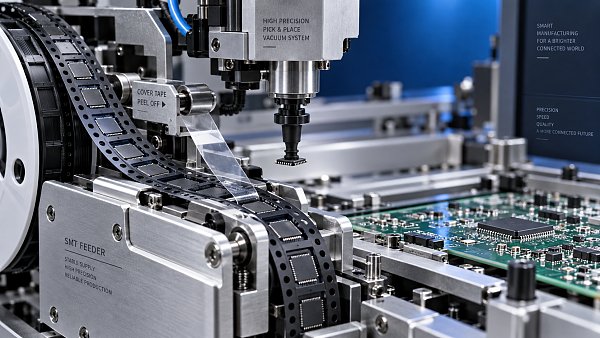
Tape-and-reel parts provide the most straightforward loading model, yet reel width, pocket pitch, cover-tape behavior, and pickup height still affect feeder choice. A line carrying many low-quantity part numbers can lose substantial time if each feeder requires a lengthy setup or if feeders cannot remain prepared off-line. Stick-fed components, matrix trays, waffle trays, and bulk-fed parts require separate capacity calculations. Count the physical feeder positions after including tray units, wide feeders, and any space reserved for special components; nominal feeder count alone is misleading.
Feeder interoperability deserves the same level of scrutiny as the placement head. A feeder fleet that cannot be shared between machines, cannot be prepared off-line, or uses incompatible reel carts creates a hidden constraint during changeover. Confirm the supported feeder widths, intelligent feeder identification, calibration requirements, splice handling, remaining-component tracking where used, and the method for transferring a prepared feeder setup to the line. The goal is controlled material readiness, not simply the ability to attach many feeders.
Rate specifications need a real-program interpretation
Compare cycle-time claims only after converting them into a representative placement program. The representative board should include the normal distribution of passives, ICs, connectors, polarity-sensitive parts, and vision-intensive packages. It should also reflect board dimensions, panel format, number of fiducials, and the intended line configuration. A machine with a fast multi-nozzle head may be highly efficient on dense resistor-and-capacitor populations but gain less advantage where the program contains frequent nozzle changes or many large, individually recognized devices.
Ask how the machine schedules pickups and placements when feeder positions are fragmented. Placement optimization works best when required components are arranged to support efficient head travel and grouped pickup sequences. High-mix work often limits that freedom because reels need to remain loaded for multiple products, feeder banks are shared among jobs, and wide reels consume adjacent positions. The quoted rate should therefore be evaluated with the feeder layout likely to be used, rather than an ideal layout built for one board.
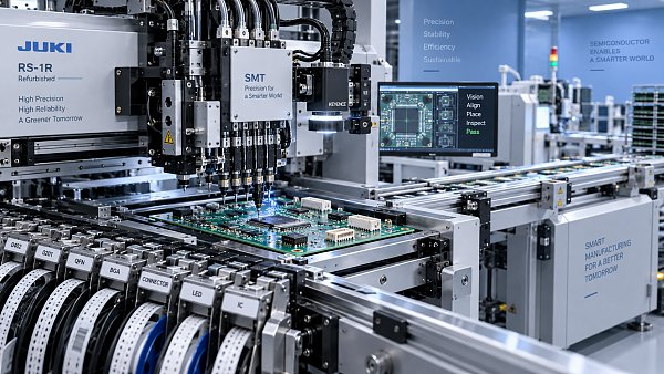
Board handling is part of effective throughput. Examine conveyor width adjustment, rail adjustment time, edge-clamp behavior, automatic width setting, dual-lane capability, buffering, and communication with upstream printing and downstream reflow. Dual lanes are useful only when the component-loading strategy, inspection flow, and downstream equipment can support two jobs without creating material confusion or long waiting periods. A single, well-balanced lane often produces a more dependable mixed-volume flow than a dual-lane arrangement that complicates setup.
Accuracy, repeatability, and process margin
Placement accuracy is meaningful only when linked to the assembly’s process margin. A broad chip component on a generous land pattern tolerates a different placement variation from a fine-pitch package on a compact footprint. The placement machine is also only one contributor to final alignment. Stencil aperture design, solder-paste deposit consistency, board support, component coplanarity, reflow behavior, and fiducial quality all influence the result.
Repeatability often matters more than a favorable single-point accuracy figure. Repeatable centering, repeatable rotation, and stable placement force make process verification easier and reduce unexplained shifts across lots. Review whether the stated accuracy applies after vision correction, whether it is specified at the board level or machine coordinate level, and whether it changes with placement speed or package type. The machine should also retain performance across the temperature conditions and duty cycle expected on the shop floor.
Vision capability requires a more detailed review than “top and bottom camera” descriptions. Evaluate component recognition for markings, leaded packages, balls, bottom terminals, odd-form geometries, transparent or reflective surfaces, and packages with inconsistent orientation features. Poor contrast, damaged tape pockets, and component variation can create false recognition failures that appear to be a machine-speed problem. Verify library creation tools, image review functions, error classification, and the ability to tune recognition without weakening controls for similar-looking parts.
For precision work, board registration must be considered alongside component recognition. Fiducials should be accessible after panelization and should remain clear of solder paste, tooling marks, and surface finishes that reduce contrast. Local fiducials may be needed where a fine-pitch component sits on a board section susceptible to dimensional variation. A placement platform with strong camera capability cannot compensate indefinitely for unstable board artwork, poor fiducial placement, or panel distortion.
Changeover is a line process, not a button press
Mixed-volume productivity often rises or falls during the period between the last acceptable board of one job and the first acceptable board of the next. Recipe loading may take little time, while physical changeover consumes much longer through feeder replacement, reel confirmation, nozzle preparation, rail adjustment, board support changes, paste setup, inspection-program selection, and first-article verification. Machine comparisons should separate automatic actions from tasks that still require manual preparation.
Off-line setup capacity is valuable when products recur. Feeder carts, feeder setup tables, barcode-based material verification, stored feeder assignments, and program-driven setup instructions reduce the chance that a short run becomes an extended interruption. Their value depends on discipline in material labeling and feeder maintenance. A well-equipped line still loses time when a reel is loaded into the wrong feeder, an expired splice is not recorded, or a feeder has worn pickup surfaces that create intermittent mispicks.
Changeover performance should be tested with a complete job transition, preferably between two genuinely different assemblies. The observation should include feeder removal and installation, verification of substitutes or alternate reels, nozzle availability, board-width adjustment, program selection, first-board inspection, and correction of any expected setup issue. A demonstration built around preloaded feeders and a prepared program reveals little about mixed-volume behavior.
Software determines whether flexibility remains controlled
Machine software must manage data consistently from the component library through the placement program and into traceability records. A library should retain package dimensions, pickup information, vision parameters, nozzle compatibility, rotation rules, polarity interpretation, feeder assignment options, and approved alternates. If each new program recreates this information independently, the line accumulates inconsistent definitions and the risk of silent errors grows.
Look for clear handling of revisions. A controlled system distinguishes a changed footprint from a changed feeder location, a changed rotation convention, and a changed approved component source. It should preserve program history and make it possible to identify which version was used for a given build. Integration with solder paste inspection, automated optical inspection, material control, or manufacturing execution systems is useful when it supports this chain of evidence. Integration that merely transfers board counts without maintaining common identifiers offers much less operational value.
Data import is another frequent source of underestimated work. CAD, centroid, bill-of-material, and panel data may use different origin points, rotation conventions, reference designators, or package naming rules. Before selecting equipment, run a sample of real engineering data through the programming workflow. Measure the effort required to map part names, validate rotations, generate fiducial strategy, and identify components needing special handling. A fast machine cannot recover time repeatedly spent correcting import assumptions.
Build the line around the limiting task
The placement machine should be sized in relation to printing, inspection, reflow, manual assembly steps, and material replenishment. A high-output mounter paired with a slow changeover at printing or a congested inspection station merely moves the queue. Conversely, a placement platform with lower headline speed may be the stronger choice where frequent product changes dominate and its feeder, software, and board-handling arrangement shortens the total interruption.
Maintenance access affects this balance. Check access to feeders, cameras, nozzles, filters, lubrication points, calibration functions, and recoverable error areas while the machine is installed in its intended line position. Required clearance around the equipment is not cosmetic; restricted access lengthens routine service and can encourage deferred maintenance. Confirm utility requirements, air quality expectations, electrical supply, floor loading, ESD grounding arrangement, and environmental limits before finalizing the layout.
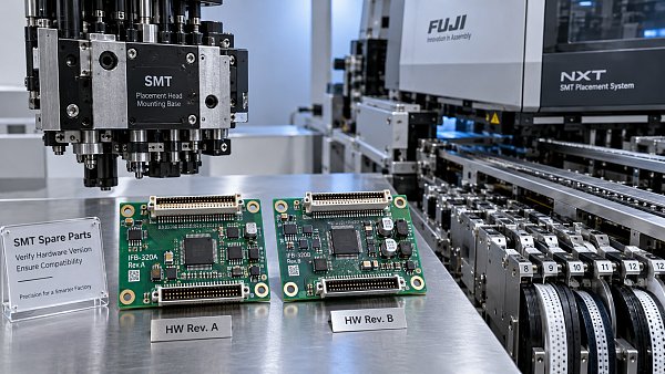
Spare-part strategy should focus on items that affect recovery time: nozzles, filters, feeder wear parts, vacuum-related consumables, camera protection components, and board-support hardware. Original specifications and controlled compatibility matter because a low-cost substitute that changes pickup height, vacuum behavior, or mechanical fit can create defects that are difficult to trace back to the part itself.
A sound selection record links each proposed configuration to the actual component mix, board envelope, feeder plan, anticipated changeover sequence, representative program result, and software workflow. That record exposes whether extra placement speed is useful capacity or merely a favorable specification. For mixed-volume production, the more durable choice is the one that keeps material, programs, boards, and placement behavior predictable as the product mix changes.


GET A FREE QUOTE
Simply fill in the information to get a free quote! Our professional team customizes photovoltaic solutions for you, provides accurate quotes, and rejects hidden consumption!