
Blog
Purchase price is a weak proxy for the real suitability of SMT assembly equipment. A machine can meet a quoted placements-per-hour figure yet fail the board because its feeder configuration cannot support the required mix, its vision system cannot reliably recognize difficult packages, its software does not preserve traceability data, or its maintenance model creates unacceptable recovery time. The useful comparison is not “which machine is faster?” but “which equipment configuration can repeatedly build this product family at the required quality, changeover frequency, and operating cost?”
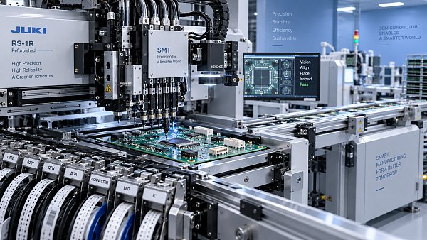
That distinction matters especially where boards contain semiconductor devices with fine pitch, small passive components, bottom-terminated packages, moisture-sensitive parts, or mixed technologies. Placement equipment, printers, SPI, reflow ovens, conveyors, inspection systems, and line-control software should be evaluated as an operating system rather than as isolated capital items. A technically strong placer cannot compensate for unstable solder paste deposition, poor board handling, or an inspection process that detects defects without providing actionable feedback.
Start with the production envelope, not the machine brochure
The comparison should begin with a documented production envelope: the boards, components, volumes, quality requirements, and operating modes that the line must support. This is more useful than a generic equipment specification because published performance is often based on favorable component mixes and minimal feeder changes.
A realistic board and component dataset should include:
- Board dimensions, thickness range, panelization method, edge-clearance requirements, warpage risk, fiducial design, and support-pin constraints.
- Component package range, from the smallest chips to connectors, shields, odd-shaped devices, BGAs, QFNs, LGA packages, CSPs, and any package-on-package or specialized assemblies.
- Package tolerances, lead coplanarity concerns, bottom-side termination geometry, component height, pickup surfaces, and orientation requirements.
- Expected annual and daily volume, lot sizes, product mix, changeover frequency, and whether the line will run one long-life product or many low-to-medium-volume assemblies.
- Required inspection coverage, serialization, material traceability, process-data retention, and engineering change control.
The data should represent difficult but normal production conditions, not only an idealized high-runner board. A line selected around a single simple board may be poorly matched to the next design revision. Conversely, buying for a hypothetical extreme package that has no credible place in the product roadmap can impose unnecessary cost and complexity.
A practical evaluation separates three categories: required capability, desirable flexibility, and unsupported complexity. Required capability must be demonstrated. Desirable flexibility should be costed and ranked. Features with no credible operational use should not dominate the decision merely because they improve a comparison sheet.
Placement accuracy must be linked to process capability
Nominal placement accuracy is commonly compared as a headline number, but its meaning depends on measurement conditions. A quoted accuracy may be based on a particular component type, placement mode, calibration state, board condition, or statistical definition. It does not automatically describe accuracy on a warped panel, a fine-pitch device with nonstandard terminals, or a component supplied in a difficult tape-and-reel format.
The relevant question is whether the machine can place the actual package-to-pad relationship within the process window allowed by stencil design, paste volume, component self-alignment during reflow, and solder-joint reliability requirements. Fine-pitch QFNs, BGAs, LGA devices, and very small passive components do not create the same placement challenge. A machine may handle one category comfortably while requiring special nozzles, vision settings, or reduced speed for another.
Compare the complete accuracy chain rather than only the motion platform:
- Board registration: fiducial recognition, local-fiducial support, board distortion compensation, camera field of view, and tolerance for production PCB variation.
- Component recognition: bottom-vision capability, lead inspection, ball or terminal pattern recognition, polarity verification, and performance with dark, reflective, transparent, or irregular surfaces.
- Pickup stability: nozzle selection, vacuum monitoring, component thickness handling, package centering, and detection of pickup errors before placement.
- Placement behavior: force control where needed, placement-height control, support for fragile parts, and repeatability at the programmed speed rather than only at a reduced demonstration speed.
For semiconductor-heavy assemblies, verify how the equipment handles package-specific exceptions. Bottom-terminated components can be sensitive to paste and placement-planarity interactions. BGAs and CSPs require confidence in ball-pattern alignment, while small passive components may expose nozzle wear, feeder pitch errors, or static-control weaknesses. The goal is not to demand identical accuracy for every package, but to establish documented, repeatable settings for the packages that define product risk.
Throughput is a line balance problem
Advertised component placements per hour should be treated as a theoretical ceiling unless the supplier can model the intended product mix. Actual output is affected by feeder loading, nozzle changes, vision time, board transfer, component availability, placement sequence, rejected pickups, and operator interventions. The useful metric is completed, acceptable boards per shift or per unit of scheduled time, not the highest placement rate reached under a simplified cycle.
Request a cycle-time study based on representative board files and a realistic feeder setup. The study should identify assumptions: number of active feeders, component pickup locations, panel count, board transfer time, use of special heads, inspection time, and expected stoppages. If a supplier uses a benchmark board, compare its package mix with the actual product family before using the result in a capacity calculation.
Line balance also changes the value of individual machines. A high-speed placer feeding a slow reflow profile, an undersized printer, or an inspection station with excessive programming time will not deliver its rated benefit. Equipment should be compared around the constraint point in the intended line. For high-mix work, changeover duration and verification effort may matter more than incremental placement speed. For stable, high-volume work, feeder density, parallel placement capability, and material replenishment design may become more influential.
Capacity planning should include a reserve for routine variation. Operating every station at its theoretical maximum leaves little room for feeder replenishment, first-article adjustments, component substitutions, planned maintenance, or recovery after faults. The appropriate reserve depends on production policy, but it should be explicit rather than hidden inside an optimistic utilization assumption.
Feeder strategy often determines whether flexibility is real
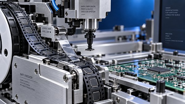
Feeder capacity is frequently reduced to the number of feeder slots. That number is incomplete. The relevant comparison includes feeder types, tape widths, pitch compatibility, intelligence features, setup verification, shared access between heads, and the practical time needed to load or replace a feeder.
A platform with many slots may still be inefficient if it requires frequent teardown for common product changes. Another system with fewer slots may support rapid offline feeder preparation, barcode verification, and repeatable feeder carts. The better choice depends on the product mix and how often production changes from one assembly to another.
Examine the entire material-delivery model:
- Support for tapes, trays, sticks, tubes, bulk feeders, and specialized packages used in the component library.
- Feeder identification and error prevention, including whether the system can verify part number, feeder position, reel identity, and remaining quantity.
- Handling of damaged leader tape, short reels, splices, nonstandard pockets, and components with poor tape retention.
- Offline setup capability and the controls that prevent an offline-prepared feeder bank from being installed incorrectly.
- Availability and interchangeability of feeders across equipment generations or multiple lines.
For devices requiring controlled storage or limited floor life, feeder logistics must also connect to material control. A technically capable machine does not solve traceability or exposure-time problems if reels can be loaded without a reliable material identity and usage record.
Software integration is part of the equipment decision
SMT assembly equipment creates value through controlled execution, not only physical placement. Software determines how reliably a CAD/BOM package becomes a production program, how revisions are approved, and whether process information can be traced after the board has shipped.
Compare the data path from engineering release to machine operation. File import should preserve reference designators, rotations, package definitions, fiducials, panel information, and approved component alternatives without introducing manual transcription. Manual edits cannot always be avoided, but they should be visible, version-controlled, and reviewable.
Program creation time should be evaluated alongside program validation. A short import process is not an advantage if it shifts the burden into extensive line-side correction. Useful software functions include component-library governance, machine-program revision control, permission management, change logs, and clear separation between engineering data and operator-adjustable settings.
Integration requirements vary by factory, but several interfaces deserve scrutiny: connections to MES or traceability systems, barcode readers, automated optical inspection, solder paste inspection, x-ray inspection where required, label printing, and material-management tools. The issue is not whether every interface exists in a brochure. It is whether the interface supports the required data fields, error states, data ownership, and recovery behavior.
Traceability should be tested as a retrieval task. For a selected serial number, determine whether the system can link the board to its production program revision, machine events, component lot or reel identifiers, inspection results, rework status, and relevant process records. If the required history is spread across disconnected systems or depends on handwritten logs, the traceability design is incomplete.
Printing, reflow, and inspection set the placement machine’s usable window
Placement quality cannot be assessed independently of solder paste printing and reflow. For fine-pitch and bottom-terminated packages, paste-volume consistency can have a greater effect on solder-joint quality than a small difference between two placement-accuracy specifications. The stencil printer should therefore be compared for board support, alignment repeatability, paste management, understencil cleaning, clamping method, and its ability to execute the required aperture and support strategy.
SPI is valuable when it is integrated into a corrective process rather than treated as a screening station. Compare measurement repeatability, false-call behavior, programming workflow, and the ability to classify defects that require stencil cleaning, paste adjustment, board support changes, or engineering review. A system that produces excessive non-actionable alarms can reduce line efficiency without improving process control.
Reflow evaluation should consider zone configuration, thermal uniformity, conveyor stability, atmosphere requirements, profile repeatability, and the capacity to accommodate board mass variation. The correct oven is not simply the one with the largest number of zones. It is the one that can produce and maintain validated profiles for the thermal demands of the assembly while fitting the throughput and board-handling requirements of the line.
Inspection coverage must match defect risk. AOI can identify many placement, polarity, solder, and component-presence issues, but its limits should be understood for hidden joints. Where hidden-joint verification is necessary, x-ray capability, sampling strategy, programming effort, and image interpretation criteria require separate evaluation. No inspection method removes the need to stabilize upstream processes.
Maintenance and serviceability should be compared before commissioning
Maintenance is often discussed after the main technical choice has been made, even though it shapes long-term availability. Compare scheduled maintenance tasks, calibration requirements, consumables, lubrication needs, wear parts, nozzle management, feeder repair arrangements, and the diagnostic tools available to production and maintenance teams.
Ask for maintenance documentation that distinguishes routine operator tasks from work requiring trained service personnel. A machine may have strong performance but be poorly suited to an operation where routine fault recovery depends on remote support or specialist travel. Diagnostic access, alarm clarity, spare-part identification, backup and restoration procedures, and training quality all affect recoverability.
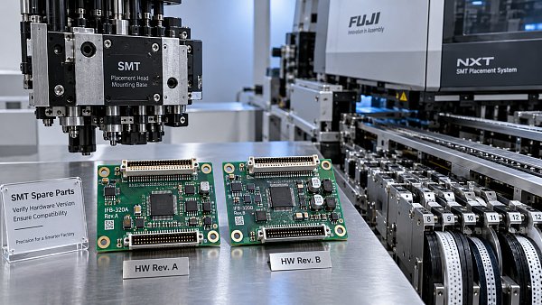
Long-term spare-parts availability deserves particular attention for original machine components, feeders, nozzles, cameras, motors, control boards, and obsolete electronic assemblies. The evaluation should identify recommended critical spares, expected lead-time risks, repair options, and whether parts are tied to a proprietary supply channel. The lowest initial quote can become costly if a common failure item is difficult to source or a feeder fleet cannot be economically maintained.
Compare suppliers through evidence, not assurances
A technical comparison becomes more reliable when each bidder responds to the same evidence package: representative PCB data, component list, volume assumptions, required interfaces, quality criteria, facility constraints, and acceptance conditions. Open-ended demonstrations tend to emphasize the best features of each platform; controlled evaluation reveals the operational differences.
Factory acceptance and site acceptance criteria should be defined before purchase order release. These criteria can include capability on designated package types, cycle time for agreed board data, feeder setup verification, communication with specified external systems, board transfer behavior, alarm recovery, and documented training deliverables. Acceptance conditions should distinguish between demonstrated machine capability and process capability that depends on customer-supplied stencil design, materials, board quality, or profile development.
Facility compatibility should not be treated as an installation detail. Electrical supply, compressed-air quality, nitrogen provision where applicable, ESD controls, temperature and humidity conditions, floor loading, access for feeder carts and service, exhaust requirements, and upstream/downstream conveyor interfaces can affect both installation scope and stable operation.
The strongest selection is usually configuration-specific
There is rarely a universally superior SMT assembly equipment platform. The best choice is the configuration that satisfies the defined component envelope, produces credible line-level capacity, supports controlled data flow, and remains maintainable through the expected equipment life. A high-speed machine with limited feeder flexibility may be the wrong answer for frequent product changes. A highly configurable line may be excessive for a narrow, stable product range. An inspection-rich system may still underperform if its data cannot drive process correction.
The most defensible decision records the assumptions behind it: board family, package range, validated throughput basis, feeder plan, software interfaces, maintenance responsibilities, spare-parts strategy, and acceptance criteria. That record is more valuable than a ranking based on headline specifications because it shows why the selected system fits the manufacturing process—and where its limits remain.


GET A FREE QUOTE
Simply fill in the information to get a free quote! Our professional team customizes photovoltaic solutions for you, provides accurate quotes, and rejects hidden consumption!