
Blog
137 machines in 2026—and counting! It is a milestone worth celebrating, and an opportunity to look closely at what equipment numbers mean on a PCB assembly floor. Each machine has a specific job, but its contribution depends on the boards, components, processes, and supporting equipment around it. The useful question behind the headline is how those individual machines fit into production that runs reliably.
The headline leaves the mix of equipment and its delivery or operating status unspecified. It therefore cannot establish installed capacity, shipment volume, or production results. What it does offer is a starting point for examining the decisions behind an equipment milestone: where capacity is needed, which configurations suit the work, and what must be ready before another machine enters the line.
Where another machine changes the output
Adding equipment creates useful capacity when it addresses a real production constraint. A faster placement machine will have limited effect on finished-board output if boards already wait for reflow, inspection, or a downstream through-hole operation. The first useful evidence is the movement of boards through the existing process: where queues form, where machines wait, and where repeated intervention interrupts the cycle.
Those observations need context. A queue ahead of automated optical inspection could reflect insufficient inspection capacity, an overly sensitive inspection program, or an upstream process producing excessive defects. Each condition calls for a different response. Additional inspection equipment addresses the first; program refinement or process correction addresses the others. Similar-looking congestion can therefore lead to very different equipment decisions.
Product mix also changes the answer. Long runs of a stable assembly place emphasis on sustained cycle time. Frequent product changes make feeder preparation, program verification, stencil replacement, and first-board approval more influential. A machine with a higher advertised placement rate can lose its apparent advantage if each changeover takes longer or requires extensive adjustment.
Before assigning value to an additional machine, establish a baseline using representative production. Record good boards completed, time spent changing products, recurring stops, and time lost waiting for material. Keep planned breaks separate from equipment faults. This gives the next machine a defined purpose and creates a fair basis for assessing its contribution after installation.
The board determines the useful specification
Equipment specifications become meaningful when connected to an actual assembly. Board dimensions alone do not describe the work. Panel thickness, warpage, component height, package mix, underside features, and available support areas all influence whether a board travels through a machine and remains stable during processing.
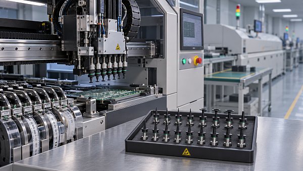
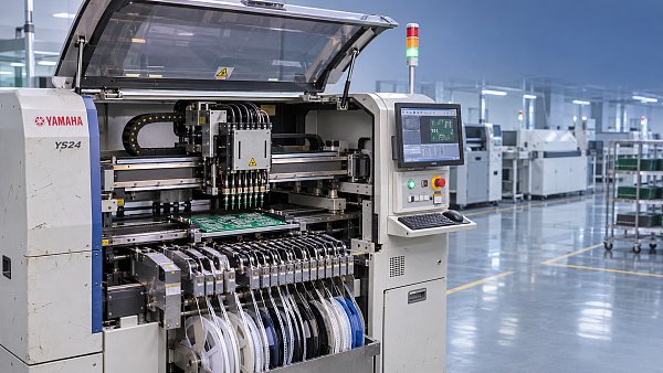
For a placement machine, maximum speed is only one part of that assessment. A board populated mainly with small passive components presents different demands from one containing fine-pitch devices, large connectors, shielding parts, and components supplied in trays. Nozzle changes, vision processing, feeder arrangement, and travel distances affect the resulting cycle. A useful comparison uses the intended component mix and the proposed machine configuration.
Feeder capacity deserves particular attention. Available feeder positions do not translate directly into the same number of distinct components: wider tape feeders occupy more space, while trays and other feeding arrangements introduce separate constraints. A configuration that supports one assembly comfortably might require feeder exchanges for another. That difference becomes significant when products alternate frequently.
Printing has its own board-specific requirements. Fine-pitch deposits demand suitable stencil apertures, stable board support, controlled separation, and effective cleaning. If a panel flexes during printing, purchasing a faster downstream machine will not correct inconsistent paste deposits. Underboard tooling must support the panel without contacting vulnerable components on its underside.
For reflow, the relevant question is whether the oven can produce an acceptable thermal profile at the intended loading. A thermally demanding assembly containing large copper areas or high-mass components behaves differently from a lighter board. Conveyor speed and temperature settings must be evaluated together with the solder paste process window and component temperature limits. Heater settings alone do not establish the temperatures experienced by solder joints.
SMT and through-hole operations share the same production schedule
A line containing both surface-mount and through-hole components needs capacity planning across both processes. Boards leaving reflow can accumulate before insertion or soldering even when the SMT section appears well balanced. The practical production rate then follows the slower downstream operation.
Through-hole assembly is especially sensitive to physical access. Connector bodies, nearby surface-mount components, lead length, and underside clearances affect soldering options. Selective soldering requires suitable nozzle access and a process that delivers adequate heating without damaging adjacent materials. Wave soldering introduces different considerations around assembly layout, component suitability, and pallet design.
Fixtures and pallets therefore belong in the equipment discussion from the beginning. They affect support, handling time, thermal behavior, and access to the joints. A machine demonstration using an uncomplicated sample board provides limited evidence for an assembly with restricted clearances or substantial thermal mass. Representative hardware makes the evaluation more useful.
The handoff between processes also matters. Buffers absorb short interruptions, but they do not resolve a persistent capacity mismatch. If work repeatedly accumulates between SMT and through-hole assembly, increasing buffer space simply stores more unfinished boards. The equipment plan needs to address the process creating the queue.
A machine description needs a configuration behind it
Two machines carrying the same model designation can differ substantially in usable capability. Installed options, software licenses, handling direction, component recognition features, feeder interfaces, and maintenance condition all affect suitability. A model name is a starting reference; the actual configuration determines what can run.
Several details deserve explicit documentation before equipment is assigned to a line:
- The proposed production setup: placement heads, feeder types, nozzle inventory, conveyor arrangement, and any options needed for the intended assemblies.
- Program transfer and software compatibility, including whether existing production data can be imported and which functions require an active license.
- Included tooling and accessories. Board supports, carts, calibration items, and product-specific fixtures can determine whether installation proceeds directly to trials or pauses for additional preparation.
- For used equipment, maintenance records and demonstrated operation under relevant conditions provide more useful evidence than appearance alone.
Condition assessment should follow the machine’s function. Placement equipment needs evidence of repeatable pickup, recognition, and placement. An oven requires attention to heating performance, conveyor operation, exhaust arrangements, and contamination. Inspection equipment needs suitable imaging capability and an evaluation against the defects of interest. A brief power-on demonstration cannot establish all of these.
Acceptance criteria work best when agreed before the demonstration. Specify the representative board or assembly, the configuration being tested, the observations to record, and the conditions that constitute acceptance. This keeps a successful trial tied to the intended application and reduces ambiguity when the equipment reaches its destination.
Spare parts turn availability into a practical question
A machine is available for production only while its essential systems remain serviceable. Replacement-part planning starts with identifying the components whose failure would stop the process and establishing how those components are specified. Part number, revision, machine serial range, connector arrangement, and installed options can all affect compatibility.
A visually similar replacement is not sufficient evidence of equivalence. This is particularly important for sensors, control boards, motors, and assemblies that interact with machine software. A component that physically fits can still produce incorrect feedback or fail to communicate. Compatibility needs confirmation at the level of the actual machine configuration.
Original parts also require precise identification. Descriptions such as “original nozzle” or “original feeder part” are incomplete without the relevant reference and application. Packaging and labels help establish identity, while condition and storage history remain separate questions. Elastomers, lubricated mechanisms, and electronic assemblies do not share the same storage concerns.
A useful spare-parts holding reflects failure consequences and replenishment time. Frequently replaced wear items belong in a different category from expensive assemblies that rarely fail. Stocking decisions should follow maintenance history and production exposure, with clear storage locations and records. An unidentified part on a shelf offers little protection during a stoppage.
Installation is part of the equipment decision
Physical fit extends beyond the machine footprint. Access doors, feeder carts, maintenance panels, exhaust connections, and material movement need space. A compact layout that blocks servicing can turn a routine adjustment into an extended interruption. Delivery access also needs attention: the route from unloading to the final position must accommodate the equipment and its approved handling method.
Utilities should be matched to the specific equipment documentation. Electrical supply, protective connections, compressed-air quality, exhaust requirements, and network access vary by machine and configuration. An available air connection does not establish adequate pressure or flow at the machine while neighboring equipment is running.
Line interfaces need the same care. Conveyor height, transfer direction, rail alignment, board-clearance limits, and communication compatibility determine whether adjacent machines exchange boards reliably. A successful standalone test does not prove that the assembled line will transfer the full product range without jams or handling damage.
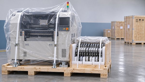
Shipping preparation and recommissioning are connected. Transport restraints, protection of moving assemblies, moisture precautions where specified, and handling records help preserve condition. After positioning, the required leveling, calibration, safety verification, and process qualification must follow the equipment instructions. Production readiness begins after these activities establish that the installed machine performs as intended.
Give the next addition a measurable job
The strongest continuation of a 137-machine milestone is a clear purpose for each subsequent addition. That purpose could be relieving a documented bottleneck, accommodating a package outside the current capability, reducing disruptive changeovers, or replacing equipment with recurring downtime. Each objective requires different evidence.
A capacity project calls for representative cycle and output measurements. A capability project needs successful processing of the relevant boards and components. A reliability project requires observation over a suitable production period, with stops recorded consistently. Combining every objective into a general promise of “better efficiency” makes acceptance difficult and obscures whether the investment achieved its intended result.
Keep the reference conditions attached to the results: assembly revision, material set, program version, tooling, staffing arrangement, and inspection criteria. When those conditions change, the comparison changes too. A repeatable record makes it possible to distinguish equipment performance from differences in the work being processed.
137 machines in 2026 is a reason to celebrate. As the count continues, the most useful next entry is one with a defined role, demonstrated suitability, and a prepared place in production.



GET A FREE QUOTE
Simply fill in the information to get a free quote! Our professional team customizes photovoltaic solutions for you, provides accurate quotes, and rejects hidden consumption!