
Blog
A stopped placement module can put a production schedule at risk while technicians determine whether the problem is a worn nozzle, a feeder fault, a vacuum leak, or a failed drive component. The practical response is to stock the parts that are both likely to interrupt production and difficult to obtain or move from another module quickly—not simply to buy a large assortment of spares.
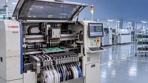
For FUJI NXT lines, the first candidates are usually the correct nozzles and nozzle-related wear parts, compatible feeder spares, vacuum and pneumatic components, selected sensors, and a small number of critical motion or control parts. The exact list depends on the installed modules and heads, product mix, maintenance capability, and confirmed part numbers. A spare is useful only if it fits the affected equipment and can be installed and verified safely.
Start with the parts closest to the placement process
Nozzles and nozzle-related wear parts
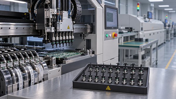
Nozzles are exposed to repeated contact, contamination, and handling. A damaged tip, blocked passage, or incorrect nozzle selection can contribute to pickup errors, dropped components, or placement problems. Because different components and head configurations require different nozzle types, a generic stock of “NXT nozzles” is not enough.
Keep verified replacements for the nozzle types used on current jobs, especially those required by high-volume products or components with limited alternative handling options. Include applicable seals, filters, or other nozzle-related service parts where the machine documentation identifies them as replaceable. Protect nozzle tips in labeled storage rather than allowing loose parts to contact one another.
Before replacing a nozzle, inspect it under appropriate magnification and follow the approved cleaning procedure. Repeated errors after a known-good nozzle is fitted may point to contamination elsewhere in the vacuum path, a feeder presentation issue, or a head problem. Avoid treating every pickup alarm as proof that the nozzle itself has failed.
Feeder assemblies and feeder service parts
A faulty feeder can interrupt a job even when the placement module is otherwise healthy. Symptoms may include inconsistent tape advance, poor component presentation, or repeated pickup errors at one position. A compatible, tested spare feeder can be a faster recovery option than repairing the original on the line.
Stocking decisions should reflect the feeder sizes and types actually used, including any special component presentation requirements. Maintain a record of feeder configuration and compatibility rather than assuming that every feeder with a similar appearance is interchangeable. For repairable feeders, hold the wear parts identified in the applicable service documentation and provide a defined route for inspection and repair.
When an error follows a feeder to another suitable position, the feeder becomes a stronger suspect. When the error remains at the original position, check the pickup location, setup, and surrounding equipment instead. Make changes under the site’s approved procedures and record the result; swapping several items at once can conceal the underlying fault.
Support the vacuum path and air supply
Vacuum performance affects the machine’s ability to pick and retain components. Blocked filters, damaged tubing, leaking seals, and faulty pneumatic devices can produce symptoms that resemble nozzle or feeder problems. Useful inventory may therefore include the machine-specific filters, seals, tubing, fittings, and valves that maintenance personnel are authorized and equipped to replace.
Start with the parts that are accessible, regularly serviced, and identified by the installed machine configuration. A selection of fittings that merely looks similar is a poor substitute for the correct specification: connection size, material, pressure rating, and intended service can matter. Check the equipment documentation before ordering or fitting any pneumatic component.
During diagnosis, compare the affected station with a known-good equivalent where the machine’s procedures allow it. Inspect for visible damage and contamination, and use the approved diagnostic functions or measuring equipment. Air pressure should be isolated and residual energy released before opening a pneumatic circuit. A replacement filter will not resolve an upstream air-quality issue or a leak elsewhere in the system.
Choose electrical and motion spares by downtime risk
Sensors, cables, drive components, motors, and control boards can stop a module, but they are not equally sensible to stock. Some are relatively easy to replace; others require configuration, calibration, specialist tools, or controlled handling. A costly board kept on a shelf without a confirmed diagnosis or installation plan can tie up inventory without improving recovery.
Use fault history and the machine’s parts list to identify components that have caused extended stoppages or have limited availability. Give particular attention to cables and connectors subject to repeated movement, and to sensors whose failure prevents operation. Inspect cable routing, plugs, and mounting conditions before concluding that an electronic part is defective.
For motors, drives, cameras, and control boards, confirm not only the part number but also any hardware revision, software, parameter, or calibration requirements. A physically similar replacement may not be ready for service. Where replacement exceeds the maintenance team’s authorization or requires specialized alignment, document the support route and keep the necessary machine and fault information available.
Match each spare to the machine that will use it
FUJI NXT lines can contain different module, head, feeder, and configuration combinations. Parts should be selected against the installed equipment rather than the line name alone. Before placing an order or transferring stock between machines, verify the details against the current parts documentation and the identification on the existing component where accessible.
- Machine and module identification: Record the relevant model and serial information, including the specific head or assembly where the part is installed.
- Part number and revision: Check the complete identifier and any documented replacement or supersession information. Do not assume a similar-looking item is equivalent.
- Application: Confirm nozzle type, feeder format, electrical connection, or pneumatic specification as applicable to the job.
- Condition and traceability: Identify whether the item is new, repaired, or removed from another machine, and retain its service status and source records.
- Installation requirements: Establish whether special tools, software settings, calibration, or a functional test will be needed before production resumes.
Keep the machine identification and part number linked in the inventory record. This reduces the chance that a technician under time pressure selects an available but incompatible item. When identification is unclear, resolve the discrepancy before ordering rather than relying only on a photograph or a short description.
Set stock levels around recovery, not shelf space
Not every part needs a duplicate beside every module. Rank candidates using four questions: How much production is affected if the part fails? Can another compatible module or spare assembly keep the job running? How long does a verified replacement take to obtain? Can the site install and validate it without outside assistance?
A frequently used nozzle may justify several protected replacements because damage or contamination can occur during normal handling. A less common control component might justify one shared spare only if the installed machines use the same verified revision and the team has a workable replacement procedure. Conversely, a part that rarely fails but has a long replenishment time and no practical workaround may deserve a place in stock.
Use actual consumption and repair records to set minimum and reorder quantities. Include the time needed to approve a purchase, receive the item, inspect it, and make it available to maintenance—not just the supplier’s quoted transit time. Review the quantities when product mix, installed heads, feeder usage, or operating schedules change.
Separate usable stock from parts awaiting repair or investigation. A feeder returned to the cabinet after an unexplained fault should not be treated as a ready spare until it has passed the site’s functional checks. The same distinction applies to electronics removed during troubleshooting: label them with the symptom and test status rather than marking them simply as defective or good.
Respond to a stoppage without losing the evidence
A spare-parts program works best when it is paired with disciplined fault isolation. The goal is to restore output without discarding clues that would prevent the same interruption from recurring.
- Capture the fault. Record the alarm, affected module or head, feeder position, component, and operating conditions. Note any recent changeover or maintenance activity.
- Secure the equipment. Follow the site’s machine isolation and energy-control procedures before accessing moving, electrical, or pneumatic assemblies.
- Check the immediate process items. Inspect the relevant nozzle, feeder, component presentation, and accessible vacuum-path elements according to the machine procedures.
- Change one suspect item when practical. Fit a confirmed compatible, known-good spare and retain the removed part with its identification and symptoms.
- Validate the repair. Complete the required setup, calibration, and functional checks. Confirm that pickup and placement performance is acceptable under the site’s release procedure before returning to normal production.
- Close the inventory loop. Record the part used, update stock, and initiate repair or replenishment. If the symptom persists, escalate diagnosis rather than continuing to replace unrelated components.
Some faults are intermittent or appear only with a particular component or feeder position. A successful restart alone does not establish the cause. Preserve alarm information and compare performance after the change so that a temporarily disturbed connection or setup issue is not recorded as a confirmed component failure.
Keep spare parts ready for use
Storage conditions affect whether a part remains usable. Keep precision nozzles and optical components protected from impact and contamination. Store electronic assemblies in appropriate electrostatic-discharge protective packaging and handle them under the site’s ESD controls. Follow manufacturer guidance for seals, adhesives, or other materials with defined storage conditions or shelf-life limits.
Label storage locations with the verified part number, equipment application, quantity, and condition. Maintain an accessible list of approved substitutions only where compatibility has been confirmed. Periodically compare physical stock with the inventory record, and check that critical shared spares have not been consumed for another repair.
Finally, distinguish replacement from preventive maintenance. Filters, seals, and other service items should be inspected or replaced at the intervals specified for the equipment and operating conditions; waiting for a failure can turn a planned maintenance task into an unplanned line stop. Review recurring alarms alongside maintenance records to identify whether the stock list needs another spare—or whether the better correction is cleaning, setup control, air-system maintenance, or repair of an underlying assembly.



GET A FREE QUOTE
Simply fill in the information to get a free quote! Our professional team customizes photovoltaic solutions for you, provides accurate quotes, and rejects hidden consumption!