Blog
In 2026, 142 SMT machines were sold, marking an equipment sales milestone in printed circuit board assembly. The figure records machines sold; it does not specify how many production lines were equipped, which machine types were included, or whether every machine has been installed and accepted. Those distinctions matter because an SMT line brings together several processes, and a single machine rarely represents a complete assembly operation.
The milestone also invites a practical question: what does a machine need to do once it reaches the production floor? The answer starts with the boards, components, production volumes, and existing equipment it must work with. A placement machine selected for a narrow component range has different requirements from one expected to handle frequent product changes, small passive components, and larger integrated circuits on the same line.
What a Machine Count Does and Does Not Show
A count of 142 machines describes sales volume, not production capacity. SMT equipment covers different functions, including solder paste printing, component placement, reflow soldering, and inspection. Even when two machines perform the same function, their usable output can differ substantially according to configuration and the product being assembled.
The figure alone does not establish the proportion of placement machines, printers, ovens, or inspection systems sold. It also does not identify equipment condition, destinations, individual transactions, or customer outcomes. Without those details, it would be misleading to calculate the number of completed lines or infer the capacity added by the sales.
For an individual installation, the more useful unit of comparison is the process requirement. A line with a capable placement machine can still be constrained by printing, inspection, board transfer, or reflow. Conversely, replacing a machine that repeatedly interrupts production can improve flow even when its published speed is similar to that of the equipment it replaces.
Matching Placement Capability to the Board
Placement speed is often the first specification considered, but a headline rate is measured under defined test conditions. Actual throughput reflects component mix, travel distances, feeder arrangements, vision processing, nozzle changes, board dimensions, and the number of placements per board. A quoted rate is therefore useful for comparing machines only when the measurement conditions are understood.
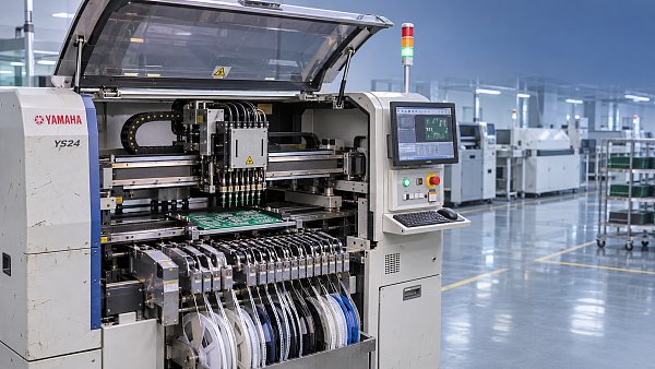
A representative board program gives a clearer basis for comparison. It should include the smallest and largest components, package heights, feeder types, placement counts, and board dimensions. If the product includes fine-pitch integrated circuits or components with unusual geometry, the relevant vision and placement capabilities need to be confirmed against those packages rather than assumed from a broad component-size range.
Feeder capacity is equally important. A machine may have enough placement speed for the required output but too few usable feeder positions for the complete bill of materials. Splitting a product across machines or changing feeder setups during a run affects line balancing and changeover time. Tape width, tray supply, stick feeders, and the available feeder configuration all influence whether the component mix can be presented to the machine as planned.
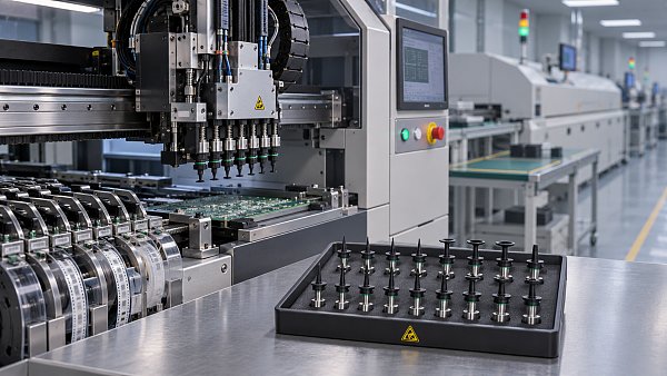
Nozzles deserve attention beyond the number supplied with a machine. Their geometry and condition affect pickup and release, especially when a product combines very small passives with larger or irregular packages. A machine that can mechanically reach a component size still needs the appropriate nozzle and a suitable vision recipe to place it reliably.
Throughput Is a Line Property
Consider a board that requires many placements but relatively little printing time. Adding placement capacity can relieve a genuine constraint. On another product, a complex stencil and demanding paste inspection may set the pace, leaving a faster placement machine waiting for boards. The same equipment specification leads to different results because the line balance changes with the product.
Cycle time should be evaluated at each process and at the points where boards accumulate or machines wait. Conveyor transfer, board stops, and inspection handling all contribute to the interval between completed boards. A machine-level cycle time that excludes loading or unloading is not directly comparable with a line-level output figure.
Product changeover also changes the calculation. A high-volume run gives setup time less weight per board, while frequent short runs make feeder preparation, program loading, stencil replacement, and first-board approval more significant. Where multiple products share components, retaining common feeders in position can reduce disruption, provided the machine has sufficient feeder capacity and the setup is controlled.
Output targets should be paired with a defined product and operating arrangement. A useful comparison states the board design, component count, expected production schedule, planned inspection, and allowance for changeovers. Without that context, a speed figure can suggest a capacity that the assembled line cannot sustain.
Equipment Condition and Configuration
The condition of a machine affects what must happen before it is ready for production. For equipment with previous service, physical appearance alone provides little evidence about motion accuracy, camera performance, feeder recognition, or the state of consumable parts. A machine can power on and still require calibration or repair before it places components within the required tolerances.
Configuration should be documented alongside condition. The machine model does not necessarily identify the installed heads, cameras, software options, feeder interfaces, or board-handling equipment. Two units with the same model designation can support different component ranges or production arrangements because their fitted options differ.
Records of maintenance and repair are useful where available. They provide context for recurring faults and replaced assemblies, although a record alone does not establish present performance. A functional demonstration using relevant components and boards gives stronger evidence than an empty motion test. For a placement machine, that demonstration can include pickup, vision alignment, placement, and inspection of the resulting board.
Original spare parts also need to be matched to the installed configuration. A part number, machine revision, and compatible assembly are more reliable identifiers than a visual resemblance. Consumables such as nozzles, filters, and feeder parts should be considered separately from major assemblies: their replacement intervals and effect on production continuity are different.
Preparing the Line Before Delivery
Installation begins with the site requirements associated with the actual equipment. Electrical supply, compressed air, exhaust, floor loading, access clearance, and environmental conditions vary by machine. An oven or other equipment requiring exhaust has different facility needs from a placement machine. A layout that fits the machine footprint on paper must also leave room for maintenance access, material loading, and board flow.
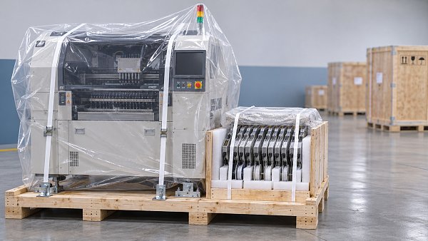
Transport and installation constraints can be easy to overlook. Door widths, lifting points, route obstructions, and the equipment's shipping configuration affect how it reaches its final position. Components secured for transport must be released according to the equipment instructions, and any removed assemblies need to be reinstalled and verified before production.
Line interfaces deserve the same attention as the machines themselves. Conveyor height and transfer direction must suit adjacent equipment. Board width adjustment, edge clearance, and support arrangements need to accommodate the actual PCB, including panels with irregular outlines or limited clearance around components. A mismatch at a transfer point can damage boards or cause stops even when each machine functions correctly on its own.
Software and data preparation should begin before the first production run. Placement coordinates, component rotations, reference designators, and package definitions need to agree with the board design and machine conventions. A program imported successfully can still contain rotation or origin errors. Reviewing a first board against the assembly documentation catches those errors before they are repeated across a batch.
From Delivery to Production Acceptance
Delivery, commissioning, and acceptance are distinct events. Delivery confirms that equipment has arrived; commissioning establishes that it is installed and functioning in its intended setting. Production acceptance requires agreed evidence that the equipment performs the specified task under relevant conditions. A sales count does not establish that these later stages have been completed.
Acceptance criteria should be tied to the equipment's function. For a placement machine, a representative trial can include the required component packages, board support, feeder arrangement, and inspection method. For a printer, the trial should reflect the stencil, paste, board finish, and apertures used in production. Oven assessment requires a suitable thermal profile for the board and components, rather than a temperature setting copied from an unrelated assembly.
Defects need to be traced to their process source. A misplaced component could originate from pickup problems, an incorrect component definition, board registration, or movement after placement. Insufficient solder after reflow may be associated with paste transfer, aperture design, storage conditions, or the thermal profile. Replacing or adjusting a placement machine will not correct every defect visible on a completed board.
Inspection results are more useful when the conditions behind them are recorded. The board revision, program version, component lots, stencil, paste, and machine settings provide context for comparison after a change. This record also separates a repeatable equipment fault from a problem introduced by a particular setup or material combination.
Once a machine is operating, routine care should follow the equipment's maintenance instructions and the production environment. Cleaning vision surfaces, monitoring feeder condition, replacing worn consumables, and verifying calibration at appropriate intervals all protect the process from gradual drift. Unusual pickup errors or recurring board-transfer stops deserve investigation before repeated resets become the normal response.
The 142-machine milestone is a sales figure; the performance of each installation is established on the line, with the intended boards and components. Clear configuration records and production-based acceptance make that distinction visible when equipment moves from purchase to regular use.



GET A FREE QUOTE
Simply fill in the information to get a free quote! Our professional team customizes photovoltaic solutions for you, provides accurate quotes, and rejects hidden consumption!