
Blog
Why Alignment Is the Quiet Variable Behind Print Stability
On a busy SMT line, solder paste printing can appear stable for several boards and then suddenly produce offset deposits, poor pad coverage, bridges, or inconsistent SPI results. Operators may first suspect paste condition, squeegee pressure, or a worn stencil. Those factors matter, but stencil alignment is often the underlying variable that turns a manageable process variation into a recurring defect.
For Solder Paste Printers, alignment is not simply the moment when the machine centers a PCB under the stencil. It is the controlled relationship between PCB pads, stencil apertures, board support, machine vision, clamping, and the mechanical condition of the stencil itself. When that relationship shifts—even by a small amount—the effective opening over each pad changes. On fine-pitch components, bottom-terminated devices, BGAs, QFNs, and densely populated boards, the allowable margin is narrow.
The practical objective is not merely “good alignment” on the first board. It is repeatable registration from the first print after setup through the last board of the production run. That is what gives operators a stable process window and keeps downstream rework from becoming a daily firefight.
What Stencil Alignment Actually Controls
A stencil aperture is designed to place a defined volume and shape of solder paste onto a defined land pattern. During printing, the PCB pad must sit in the intended position beneath that aperture. If the stencil is shifted relative to the board, paste may still be deposited, but the deposit is no longer centered or properly formed.
Alignment error therefore affects more than visual appearance. It changes how the paste overlaps the copper pad and solder mask opening. Depending on the component geometry and direction of the offset, the result may be:
- Insufficient pad coverage, where part of the aperture opens over solder mask rather than the pad.
- Off-center deposits, increasing the risk of solder balling, opens, or placement-related defects.
- Bridging between fine-pitch leads when paste is shifted toward adjacent pads.
- Uneven paste release, especially when an aperture is only partially aligned with the target land.
- Variable solder joint formation, which may not be visible until reflow or inspection.
A useful distinction for operators is this: aperture alignment does not always change the theoretical stencil volume, but it can change the usable deposit on the pad. In other words, a printer may be applying paste through the correct aperture, while the board receives an incorrect pattern. This is why a board can pass a quick visual glance yet create defects later in placement, reflow, or X-ray inspection.
Registration Is a System, Not a Single Printer Setting
Modern Solder Paste Printers can align boards with impressive repeatability, but the machine can only correct what it can reliably see and physically control. A clean fiducial image does not compensate for a warped PCB. A perfectly supported PCB does not solve a stretched stencil. Stable printing comes from treating the whole registration chain as one system.
PCB fiducials and vision recognition
Global fiducials establish the board’s overall position, rotation, and scale reference. Local fiducials provide a more accurate reference for fine-pitch component areas where dimensional variation across a larger board may matter. When a production job relies only on global alignment for a dense, fine-pitch region, a board may look acceptably registered at one end while showing a consistent offset at the other.
Fiducials must be clean, uncovered, and suitable for the printer’s vision system. Oxidation, residue, scratches, solder mask encroachment, reflective finishes, or nearby silkscreen can reduce recognition reliability. The machine may still complete its alignment cycle, but the calculated position can become less dependable or take longer to confirm.
Operators should also verify that the programmed fiducial type, diameter, illumination, and search window match the actual PCB. A program copied from a similar product can be a hidden source of instability when the fiducial finish or surrounding artwork differs.
Stencil fiducials, mounting, and frame condition
The printer aligns the board to the stencil reference, so the stencil must remain mechanically stable in its frame and in the printer clamps. Bent frames, uneven tension, damaged edges, poor clamping, or contamination under the frame can introduce a shift that is difficult to spot during setup.
Frameless foil systems require particular care. The foil must be tensioned evenly, seated correctly, and free from wrinkles or edge damage. A foil that is not held consistently may appear aligned before printing but move slightly as the squeegee traverses the stencil. That movement can show up as direction-dependent offset: deposits look acceptable in one print direction or area of the board, then drift elsewhere.
Stencil apertures also need inspection. Burrs, deformation, blocked openings, and paste buildup can imitate an alignment issue. Before changing offsets repeatedly, confirm whether the observed defect follows the pad location because of registration, or follows a specific aperture because of stencil condition.
Board support and PCB flatness
Board support is one of the most underestimated alignment controls. If the PCB bows downward between support pins or support blocks, its top surface does not stay in the same plane as the stencil. The printer may align correctly at the fiducials while component pads in unsupported areas sit lower, tilted, or displaced relative to the apertures.
This is especially relevant for thin PCBs, large panels, routed panels with weak rails, and boards carrying heavy copper distribution. A support pattern that works for one product may be unsuitable for another. The goal is to support the PCB close enough to critical print areas to prevent deflection without placing supports under components, depaneling features, or fragile regions.
Vacuum support, dedicated tooling, and properly arranged support pins can all help, depending on the printer and board design. The key is consistency: the board should locate in the same plane every cycle, not merely remain “generally flat.”
Why Small Offsets Become Major Problems on Fine-Pitch Assemblies
Alignment tolerance must be judged against the pad and aperture geometry, not against what looks small to the eye. An offset that has little consequence on large chip resistors can consume a significant portion of a fine-pitch lead pad. On QFN perimeter pads, it can move paste toward the package body or away from the outer pad edge. On BGA sites, it may reduce symmetry across the array and complicate interpretation of SPI data.
The same absolute offset can also have different consequences in the X and Y directions. If a narrow rectangular aperture is shifted across its short axis, pad coverage changes more quickly than when it is shifted along its long axis. This is why operators should not accept a generic “within tolerance” assumption without reviewing the most sensitive device locations.
For critical designs, use SPI not only to review paste volume but also to study deposit position, area, and shape. A stable average volume can hide a positional trend. If deposits across an entire board move in the same direction, investigate global registration. If only one area moves, look for local fiducial, PCB warp, support, or stencil distortion issues.
Common Alignment Patterns and What They Usually Indicate
The Interaction Between Alignment and Print Parameters
It is tempting to correct poor print results by changing squeegee pressure, speed, separation speed, or snap-off settings. These settings influence paste roll behavior, aperture filling, and release, but they should not be used as substitutes for correct registration.
For example, raising squeegee pressure may force more paste through some apertures, making a marginal deposit look better in SPI. Yet if the aperture is shifted over solder mask, increased pressure does not restore proper pad alignment. It can introduce other problems, including scooping, smearing, excess residue, or accelerated stencil wear.
Similarly, a slow separation profile can improve paste release on challenging apertures, but it cannot correct a board that is flexing away from the stencil during printing. The most reliable approach is to establish alignment and support first, then optimize print parameters based on paste type, stencil design, and deposit requirements.
Underside stencil cleaning deserves attention as well. A cleaning cycle can remove contamination that would otherwise create bridging or poor gasketing. However, if the wiping process is overly aggressive, the stencil or frame is not firmly retained, or the board is reintroduced inconsistently afterward, apparent alignment variation may follow. Watch the process before and after cleaning rather than assuming cleaning is always neutral to registration.
A Practical Alignment Verification Routine for Operators
Before releasing a new setup or restarting after a stencil change, take a short but disciplined verification approach. It is faster than sorting defects later.
- Inspect the PCB locating features. Confirm that rails, tooling holes, and fiducials are clean and undamaged. Check whether the board sits naturally in the conveyor and tooling rather than being forced into position.
- Inspect the stencil before loading. Look for damaged apertures, bent foil edges, residue, frame distortion, and signs of poor tension or handling damage.
- Confirm support contact. With the board in position, verify that support pins or blocks contact the intended locations. Pay close attention to the center of large boards and fine-pitch areas.
- Run alignment verification at critical locations. Do not judge only from one corner. Review features near the center and opposite ends of the PCB, particularly where the smallest pads are located.
- Print and inspect the first article. Use SPI when available, reviewing positional offset and paste area in addition to volume and height. If SPI is unavailable, inspect under adequate magnification against known-good reference criteria.
- Repeat after a few cycles. A single successful print proves setup, not consistency. Check whether the same positional result is maintained after the board has loaded, printed, separated, and cleaned through several cycles.
Documenting the approved support layout, fiducial settings, stencil ID, and proven printer offsets in the job record makes future changeovers less dependent on memory. It also helps the next operator distinguish a real process change from a setup variation.
Do Not “Chase” an Unstable Process with Offset Corrections
A common production-floor mistake is to enter a manual X/Y correction whenever deposits appear shifted. A correction is appropriate when the cause is understood and stable—for example, a confirmed, repeatable program-to-stencil reference difference. It is risky when the offset changes between boards or appears only in certain regions.
If operators keep adjusting offsets to chase variable results, the printer may be tuned to one board while becoming worse for the next. Instead, identify whether the variation is global, local, cycle-dependent, or stencil-specific. This classification narrows the investigation quickly.
When the shift is global and repeatable, verify the program reference, fiducial recognition, and stencil mounting. When it is local, inspect board flatness, support, local fiducials, and panel behavior. When it varies by cycle, focus on loading, clamping, support contact, and any mechanical movement during printing or cleaning.
Alignment Control Supports Process Standards, Not Just Appearance
Process standards and customer acceptance requirements often emphasize solder joint quality after assembly, but stable printing is where many of those outcomes are protected. Guidance associated with stencil design, paste printing, and component assembly—such as IPC-oriented process practices—should be translated into the actual controls used at the printer: defined setup checks, traceable stencil handling, first-article verification, SPI feedback, and response limits for positional drift.
There is no single universal offset limit that applies to every PCB. The practical limit depends on pad geometry, aperture reduction, pitch, component type, solder mask design, and the downstream process window. The most defensible standard is one tied to the product’s most sensitive features and validated through print inspection and assembly results.
Keeping the Printer, Stencil, and Support System Ready
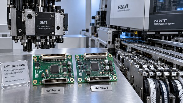
Print consistency depends on routine care as much as initial setup. Clean vision windows and camera areas, inspect board clamps, verify conveyor width repeatability, maintain support tooling, and handle stencils in a way that prevents bending and aperture damage. Spare parts that influence motion, clamping, cleaning, and vision should be specified correctly; a small mechanical wear issue can become a recurring registration problem.
For production teams sourcing SMT/THT assembly equipment, original spare parts, or complete PCB assembly line support, SMT MALLS can help connect printer-related equipment needs with the broader line requirements. The important point is to evaluate the printer as part of a process chain: board loading, support, printing, inspection, placement, and reflow all reveal whether registration is genuinely under control.
When stencil alignment is stable, operators gain something more valuable than a cleaner first-board inspection: confidence that the process will continue to behave predictably. That confidence reduces unnecessary parameter changes, shortens troubleshooting, and gives every subsequent stage of the SMT line a better starting point.



GET A FREE QUOTE
Simply fill in the information to get a free quote! Our professional team customizes photovoltaic solutions for you, provides accurate quotes, and rejects hidden consumption!