
Blog
Fuji/JUKI/Yamaha Analysis of Common Faults in Semiconductor Component Assembly
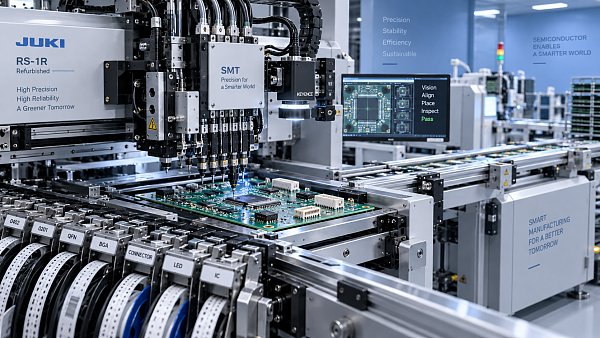
Fuji, JUKI, and Yamaha placement machines are widely used where speed, repeatability, and stable handling of small semiconductor components matter. In a modern SMT line, however, a placement machine fault is rarely just a machine fault. A feeder error can become a missing-component defect; a vision issue can appear as polarity failure; a nozzle problem can turn into intermittent placement drift that is difficult to trace after reflow.
The difficult part is that many alarms point to the last operation that failed, not necessarily the original cause. An “inspection error” may begin with poor tape indexing. A “pickup error” may be caused by a worn nozzle, but it may also come from inconsistent component pockets, excessive static charge, vacuum leakage, or a feeder that is not seated correctly. Product engineers and maintenance teams get faster results when they diagnose the full material-to-placement path instead of replacing parts at random.
This practical review focuses on common fault patterns seen on Fuji, JUKI, and Yamaha SMT platforms when assembling semiconductor components such as ICs, QFNs, BGAs, LEDs, diodes, MOSFETs, small passive devices, and other package types that demand reliable pickup and placement. Machine interfaces, feeder designs, and maintenance procedures differ by series, so final settings should always follow the applicable machine manual and the actual component package data.
Do Not Treat Every Placement Alarm as a Machine Failure
When a line stops repeatedly at one feeder position, the obvious reaction is often to exchange the feeder. That can be useful as a quick isolation test, but it does not prove that the feeder itself is defective. The same symptom can follow the reel, the component lot, the program, or the nozzle. Experienced operators usually ask a simpler question first: does the fault stay with the feeder slot, the feeder unit, the reel, or the component part number?
Moving the suspected feeder to another slot, loading a known-good reel, or assigning the component to another compatible pickup head can reveal the direction of the problem quickly. This is especially valuable for semiconductor packages with reflective surfaces, unusually thin bodies, exposed leads, or inconsistent tape presentation. These parts may pass pickup tests intermittently, making the defect look like a random mechanical issue when the real problem is material handling.
The three brands share the same broad operating logic: feed the component accurately, pick it with stable vacuum, inspect it correctly, and place it without losing positional control. The fault language is different from one platform to another, but the physical causes are familiar across all of them.
Feeder Faults: The Most Common Starting Point
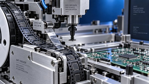
Feeder-related problems account for a large share of recurring placement interruptions. On Fuji, JUKI, and Yamaha machines, operators may see pickup failures, pitch errors, feed errors, component-present errors, or repeated recovery attempts at the same station. In many cases, the feeder mechanism is functioning normally but cannot compensate for poor tape condition or unsuitable setup.
A typical issue is incorrect tape advancement. If the pitch setting does not match the carrier tape, components may not arrive at the pickup position consistently. This becomes more visible with narrow tapes and small packages, where even a slight offset can leave the component partly under the cover tape or outside the nozzle’s effective pickup area. Damaged sprocket holes, curled tape, excessive reel tension, and loose cover tape can create similar symptoms.
For semiconductor components, do not overlook packaging quality. A reel can look acceptable at the beginning yet become problematic near a splice, after poor storage, or where the tape has been manually repaired. Components that shift within the pocket may still be picked successfully, but their orientation or centering result can become unstable. If a fault appears only after several hundred placements, inspect the physical tape section rather than relying solely on feeder diagnostics.
A common mistake is increasing pickup retries until the machine runs. That may hide the immediate alarm, but it usually reduces output and can introduce unstable quality. If a component needs repeated recovery attempts, the process is already telling you that something is outside its normal operating window.
Nozzles, Vacuum, and Pickup Stability
Nozzle problems are deceptively simple. A worn, cracked, blocked, or contaminated nozzle can generate obvious pickup errors, but not every bad nozzle produces an alarm. Some continue to pick components while shifting them slightly off-center or releasing them inconsistently during placement. This is more concerning with fine-pitch QFNs, compact IC packages, bottom-terminated components, and parts with low surface area available for vacuum contact.
Vacuum performance should be checked as a system. The nozzle is only one point in the path. Filters, valves, tubing, head connections, and maintenance condition can all influence pickup consistency. If several nozzles on one head show unstable pickup, replacing a single nozzle may not solve the actual fault. A shared vacuum issue, contamination in the air path, or a head-specific mechanical condition may be more likely.
Nozzle selection also deserves more attention than it often receives. The smallest possible nozzle is not automatically the best choice. A nozzle must match the component body, pickup surface, package stiffness, and machine process requirements. An overly small pickup area may be vulnerable to package warpage or surface contamination. A nozzle that is too large can interfere with adjacent tape features, component leads, or vision recognition.
For lines running multiple package families, controlled nozzle management is worth the effort. Keep used and verified nozzles separate, record recurring defects by nozzle type, and avoid returning visibly damaged parts to general stock. Original or correctly specified replacement nozzles matter because small variations in geometry, concentricity, or material condition can affect high-speed placement behavior.
Vision System Errors Are Often Process Errors in Disguise
Vision systems on Fuji, JUKI, and Yamaha machines are designed to verify component position, angle, dimensions, and, depending on the process configuration, polarity features. When recognition fails, teams sometimes assume the camera or lighting module needs replacement. That is possible, but it is not the first conclusion to make.
The basic question is whether the machine is seeing a bad image or applying the wrong recognition rule to a good image. A component may be correctly picked but fail inspection because its library data does not account for a chamfer, lead shape, exposed pad, laser marking, or reflective package surface. Different suppliers can provide nominally equivalent components in packaging that looks slightly different to the camera. This is particularly relevant when alternate-approved component sources are introduced without a full program review.
Dirty optics, unstable lighting, and debris on the vision window can certainly cause gradual recognition problems. So can poor board support or vibration, which may appear later as placement offset rather than an inspection alarm. Before changing thresholds aggressively, inspect the actual captured image if the machine permits it. A recognition parameter adjusted only to “pass” a questionable image can allow real polarity or centering defects into production.
For polarized semiconductor devices, the verification strategy should reflect the risk. A diode or LED with a faint marking may require more careful programming than a clearly marked package. For ICs, pin-1 identification should not rely on assumptions carried over from another vendor’s package drawing. The approved component documentation and the actual reel should agree before the line is released.
Placement Accuracy Problems: Separate Machine Offset from Board Movement
When components are consistently offset on the PCB, it is tempting to recalibrate the machine immediately. Calibration may be necessary, but board-side causes should be checked at the same time. Poor PCB support, warped boards, unstable clamping, conveyor width errors, and incorrect fiducial recognition can all create placement shifts. If the board moves slightly between recognition and placement, the machine may be operating correctly against an unstable reference.
The defect pattern provides useful clues. If all components shift in a similar direction on one board, look at board alignment, fiducials, conveyor transport, and support tooling. If only one component type is offset, focus on the nozzle, package recognition, feeder presentation, and its placement data. If the error occurs only on one placement head, head calibration or mechanical condition becomes more relevant.
Fine-pitch semiconductor packages leave little room for casual adjustments. A placement correction that improves one footprint can make another worse if the root cause is not understood. It is better to validate with controlled boards and inspect the entire pattern than to judge success from one visually acceptable component.
Conveyor, PCB Handling, and Transfer Alarms
Conveyor alarms may seem separate from component placement, but they can affect yield just as directly. Boards that arrive skewed, stop inconsistently, or are clamped under stress may lead to fiducial errors, placement offsets, and damage to sensitive assemblies. Common checks include rail width, belt or chain condition, stopper operation, sensor cleanliness, transfer timing, and the condition of board support pins.
A board that occasionally fails to enter or exit the machine may be exposing an upstream or downstream interface issue rather than an internal conveyor fault. In linked SMT lines, avoid diagnosing equipment in isolation. Transfer settings, board dimensions, panel stiffness, and communication timing need to be considered across the connected machines.
A Better Troubleshooting Sequence for Fuji, JUKI, and Yamaha Machines
A disciplined sequence prevents lost time and unnecessary spare-part consumption. Start by preserving the evidence: note the alarm text, feeder position, nozzle number, component reference, board side, and whether the issue is constant or intermittent. Then inspect the physical component, tape, feeder seating, nozzle condition, and pickup point before changing software settings.
After that, use substitution carefully. Exchange one variable at a time: a known-good feeder, another reel, another nozzle, or another machine position where appropriate. If multiple variables are changed together, the line may recover but the actual cause remains unknown. That uncertainty comes back later, often during a rush order or a product changeover.
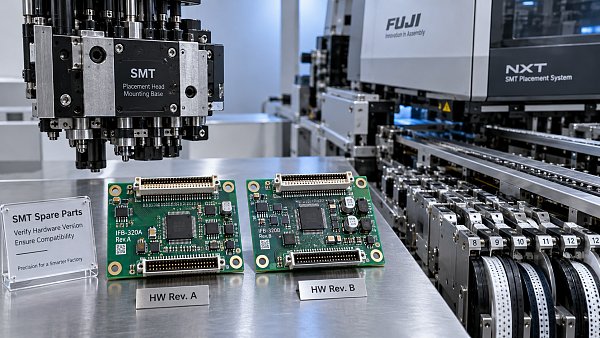
Maintenance teams should also distinguish between consumables and machine-critical spare parts. Nozzles, filters, feeder accessories, sensors, belts, and other frequently handled items need regular condition control. For more critical replacements, part compatibility, machine revision, and original specifications should be confirmed before installation. A part that physically fits may not always provide the expected operating accuracy or electrical behavior.
SMT MALLS supports SMT/THT assembly equipment, original machine spare parts, and complete PCB assembly line solutions. In fault situations, the useful value is not simply having a replacement part available; it is helping ensure that the selected feeder, nozzle, sensor, or related component matches the machine configuration and the real production requirement. That distinction matters when uptime pressure encourages quick but poorly verified substitutions.
The Most Useful Habit: Track Repeating Fault Patterns
One isolated alarm can be an accident. A fault that returns at the same feeder, with the same package family, after the same number of placements, or on the same head is a pattern worth documenting. Basic records of alarm history, component lot, feeder ID, nozzle ID, and corrective action can turn a vague maintenance problem into a solvable process issue.
For Fuji, JUKI, and Yamaha equipment, the fastest path to stable production is usually not a more aggressive machine setting. It is a clear link between material condition, feeder performance, pickup quality, vision recognition, board handling, and verified spare-part condition. When that chain is checked in order, many “mysterious” faults become ordinary, fixable production problems.


GET A FREE QUOTE
Simply fill in the information to get a free quote! Our professional team customizes photovoltaic solutions for you, provides accurate quotes, and rejects hidden consumption!